go-e Controller Setup via Display
Once the go-e Controller has been installed, you can set it up either via its display or in the go-e App.
In this article, we will explain step by step how to set up the go-e Controller using its display.
Do you want to allow Integration of youtube videos?
Allows the playback of videos, that are hosted on youtube.com. By allowing this feature, you accept the privacy agreement of google.
1. Main Menu and Navigation
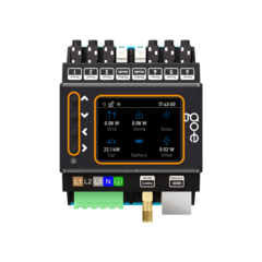
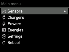
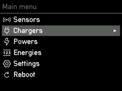
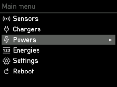
Use the four buttons next to the display of the go-e Controller to move through the menu on the display. You can access the main menu by pressing the > key without selecting a category. Use the up and down keys to navigate between the individual menu items.
If you want to select one of the menu items, press the key with the arrow pointing to the right (>) again. If you want to navigate back, press the button with the arrow pointing to the left (<).
2. Device Settings
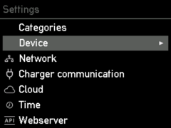
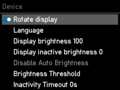
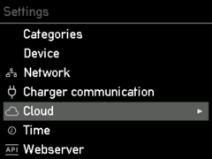
To change the language or other settings of the go-e Controller to your preferences, go to "Settings" in the main menu and then to "Device".
Here you can, for example, rotate the display of the Controller if you have mounted it rotated by 180 degrees, change the language or, if desired, adjust the brightness of the display.
3. Adjusting the Sensors
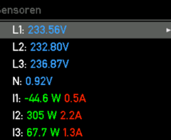
In the menu option "Sensors" you can configure the sensors and read voltages, currents and power in real time.
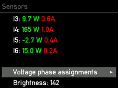
L1 to L3 shows the voltage of the phases connected to the connection terminal and N the connected neutral conductor. I1 to I6 shows the values of the connected sensors or current transformers. I here corresponds to the designation Internal, which is consistent with the connected sensor.
3.1 Sensors: Voltage settings
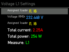
If you select L1, L2, L3 or N, you will be forwarded to the voltage settings of the phase. In this overview you can see all measured values of the sensors of the selected phase. Check whether the voltage is approximately correct. If the current and total power are not yet correct, this is not a problem, because we will come to this configuration later in this manual.
Press the button with the arrow pointing to the left (<) to return to the sensor overview.
3.2 Sensors: Load settings
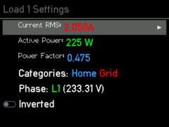
If you select one of the six current sensors in this sensor overview, you will be forwarded to the corresponding load settings.
If you have not connected a current transformer with the arrows in the direction of the current, you can invert a load via the slider.
For the power calculation to be correct, the phase must be set accurately. Imagine that the sensor measures 2 amps on your mains connection, but without a voltage reference you do not know whether you are feeding power into the mains or drawing power from it.
Note that the power should always be positive when drawing from the grid. With a solar inverter or an AC battery, the power should be positive in feed-in mode, but if the battery is being charged or the inverter has more standby consumption than generation, the power may be negative. If no energy is being consumed, the power should be close to zero.
It is very important that the correct phase is set as the voltage reference. You can find out which phase you have connected the sensor to by tracing the cables in the switch cabinet. Alternatively, you can use a multimeter to check whether the voltage at the go-e Controller matches the fuse of the load.
The power factor can be between minus one and plus one.
Minus one means maximum feed-in or charging for a battery without reactive power, plus one means maximum draw or production of energy. If the power is particularly low, the power factor is not very meaningful. For a pure resistive load, the power factor should be close to one.
To check the voltage allocation, you can switch on a large consumer with heating elements in your household, e.g. a fan heater, a hairdryer or an electric oven. If your electric oven is connected to a three-phase system, checking is especially easy because all phases are directly loaded with a power factor of almost one. If the power factors on one, two or all three phases are incorrect and are, for example, only plus or minus one third or two thirds, you must adjust the allocation. As long as the allocation is not correct, the go-e Controller cannot distinguish between feed-in and mains supply and the PV surplus control will not work.
3.3. Sensors: Assign categories
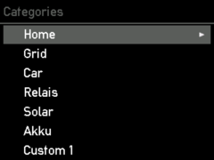
Now we come to the categories, because the go-e Controller does not yet know which sensor you have mounted where; you set that with the respective category.
There is the category "Mains". This category is the most important, because go-e Charger and go-e Controller try to regulate it to as close to zero as possible during PV surplus charging.
Let's take a look at three examples.
Example 1:
If you have mounted the corresponding sensor directly on one phase of the mains connection, you should set the Mains category to one. If you do not measure your household consumption separately, you should also set the Home category to one. This way, the entire current of the measured line is directly assigned to mains supply and household consumption.
If you have mounted a sensor on the line of a PV inverter, you can assign the power directly to the solar category. The power should be positive when the inverter is producing solar power. If you have a single-phase or three-phase inverter and measure all phases, select factor 1, but if you have a three-phase inverter and measure only one phase, you can select factor 3, the Controller will then assume 3 times the measured power, since we only measure one third.
Now you assign the solar power to the home category. Let's take a look at this calculation example:
-
Grid: we draw 1 kW from the grid
-
Solar: we generate 500 W of solar energy
We have already allocated 1 kW of grid consumption to Home. However, since we produce another 500 W ourselves, the total power we consume in the house is 1.5 kW. Therefore, please also assign the solar inverter to the Home category with the factor 1 or 3, depending on the number of measured phases of the inverter.
Example 2:
Let's assume you measure the load branch and the inverter on all phases.
You subtract the solar production from "grid" by setting the factor to minus one.
If you simply measure a load, for example a boiler, you can assign it to a custom category, for example "Custom 1". You can rename the category later. It is not necessary to assign it to Mains or Home, as you are already measuring these currents.
Now we come to our third example.
Example 3:
If your solar inverter is connected to other loads too far away from the control cabinet with the go-e Controller, you cannot measure it directly. As already mentioned, this does not matter for PV surplus charging.
If you still want to measure the solar production, you can also buy a second go-e Controller and connect it to the first one via the home network. The connection of two Controllers is currently not yet possible (as of 30.5.2023).
After you have recognised the correct categories, you can set them in the menu. In the submenu, define the factor with which your sensor value is to be taken into account in which category. For a three-phase mains connection, repeat the assignment made for Internal 1 for the sensors Internal 2 and 3.
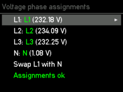
4. Optional step: Voltage phase assignments
This step is optional, and only necessary if you have not connected the voltages to the terminal on the go-e Controller as you recognise them in the control cabinet as phase 1, 2 and 3. If you have already set up your sensors correctly, this step is irrelevant.
If you select "Sensors" in the main menu, you can change the voltage phase allocations by navigating all the way down. Navigate between the lines and select the phase you want to change the allocation for with the right button to correct your incorrectly connected phase(s).
5. Network Settings
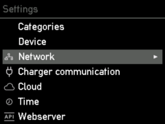
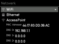
To connect your go-e Controller to your network and your go-e Charger via Wi-Fi or LAN, select "Network" under Settings.
Enter the access data for your WLAN here or configure your Ethernet or LAN to ensure a connection of the Controller to the network and to go-e Chargers.
Note that a network connection is absolutely necessary for PV surplus charging or dynamic load management. In addition, you can then connect to the Controller locally without the cloud via the go-e app.
Tip: The WiFi and Ethernet settings can perhaps be adjusted even more conveniently via the go-e app.
6. Connect go-e Controller with go-e Charger
To connect your go-e Controller to one or more go-e Chargers, select "Chargers" from the main menu.
Note that you can basically connect as many go-e Chargers as you want.
In order for the go-e Chargers to be displayed under the menu item "Chargers", the go-e Controller must be in the same network as the go-e Chargers. As already mentioned, you can configure the network in the main menu under "Settings".
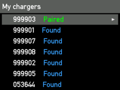
All available go-e Chargers are displayed in the "Chargers" overview. If a go-e Charger is displayed as "Paired", it is already communicating with the go-e Controller. If the go-e Charger says "Found", the wallbox is not ready to communicate with the Controller.
This may be because the automatic search for a go-e Controller is not activated in the settings of the go-e Charger app for the corresponding Charger or the Charger is already connected to another Controller. This is because each Charger can only be connected to exactly one Controller.
If you have already connected a go-e Charger, "Paired" would be displayed.
If you select a connected Charger, you will receive further information about its current charging status, such as the current rating, the voltage, etc.
Please note that you cannot change any settings for the charging process or dynamic load management here. You must do this directly in the go-e app.
7. View Category Performances
If you would like to see the current performance of the individual categories, select "Powers".
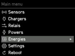
If you select "Energies" in the menu, you will see the current energy in Wh for the individual categories.
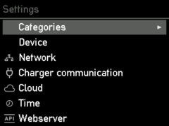
Under "Settings" you can make settings such as the time settings, cloud settings, network settings and other device-specific settings.
If you want an overview of the performance and power data of the individual categories, you can do so here under "Categories".
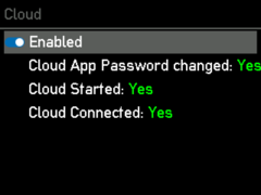
For some functionalities and depending on the go-e Charger, you may need a cloud connection. To do this, select "Cloud" in the Settings menu to activate or deactivate the connection to the cloud.
8. Settings for Experts and/or Integrators
If you are an expert or integrator and want to go wild and activate the local HTTP API, establish an MQTT or MEC meter connection or activate Modbus, you can also do this on the go-e Controller display.
Additional information:
