go-e Controller Installation: How-To Guide
The go-e Controller has to be installed by a qualified electrician, as installation must be carried out in accordance with the applicable local, regional and national regulations.
The go-e Controller comes with a quick reference guide that must be read before installation. In addition, you will find the complete installation and operating instructions, as well as the data sheet for the Controller, on our website. Both are also required to be read before installation.
Let's start with the basic installation.
Do you want to allow Integration of youtube videos?
Allows the playback of videos, that are hosted on youtube.com. By allowing this feature, you accept the privacy agreement of google.
Installing the go-e Controller in 8 Steps
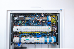
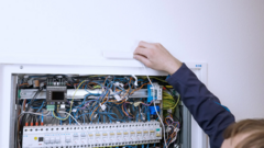
As an installation location, we recommend an electrical installation distributor that offers room for at least the four division units of the go-e Controller and some space for a new fuse.
Alternatively, it is also possible to install the go-e Controller in a new surface-mounted / flush-mounted distributor next to it and lay the connection cables for the voltage measurement and the current transformer there.
Step 1:
Use the five electrical safety rules to ensure that no voltage is present.
Step 2:
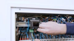
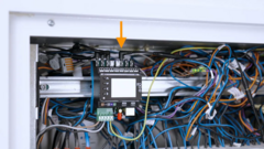
Mount the go-e Controller on the DIN rail. You can have it rotated 180° if you want. The rotation is not a problem since the display can be rotated too.
Step 3:
In the next step, connect the go-e Controller to a single-phase or three-phase supply.
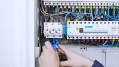
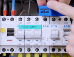
The go-e Controller requires almost no power at all and can, therefore, also be connected to a fuse with another consumer, for instance, an electric oven. If this is not possible, you must install a new fuse. Be sure to observe local installation standards when doing this. Now insert the conductors into the connection terminal of the go-e Controller and fix them with a screwdriver. You also need to connect the neutral conductor and the protective conductor.
Step 4:
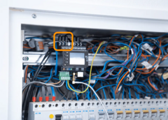
For a three-phase connection, plug the jack plugs of three current transformers into the designated inputs for current measurement. For example, in sensors one to three. With a single-phase connection, you only need to use one current transformer.
Step 5:
Next, attach the current transformers.
For PV surplus optimisation, you need enough sensors to measure the power from or to the grid. The easiest way is to measure directly at the grid connection. However, it is also possible, for example, to measure the load branch and the PV inverter separately; the Controller can add or subtract this.
In most cases, you can measure it directly at the grid connection; this is the most straightforward way. Here, you need to use three current transformers. The easiest way is to connect phase 1 to sensor 1, phase 2 to sensor 2 and phase 3 to sensor 3.
The two arrows on the current transformer must point toward the current. When connecting to the electricity grid, which we call the "mains", the arrow should point from the mains towards the house.
In the case of a solar inverter or an AC battery, the arrow should point from the inverter or battery to the distribution board.
When measuring other loads, such as a boiler, the arrow should point in the direction of the load.
If, for reasons of limited space, it is not possible to attach the current sensors with the arrow pointing in the specified direction, the sensors can also be inverted via the menu of the go-e Controller or the go-e App. In this way, the measurement of the current flow can be reversed, and correct values measured.
Let's take a look at how you can connect your PV system, battery storage, or other electrical loads to the go-e Controller.
Step 6:
After you have taken the direct measurement at the grid connection, you can use the remaining 3 to 5 current transformers to measure the current flows of different devices or consumer groups in your house.
If you want to measure and visualise your PV production, you must always measure the current using a sensor on one phase of your AC-PV inverter.
Reminder: PV optimisation is also possible without direct measurement of the production by the inverter. However, with your AC inverter, you can additionally see how much electricity it produces in total with a sensor.
If you have a battery storage system to be considered when optimising power consumption, use a current transformer to measure one phase of the battery storage. Be careful because this is only possible with AC battery storage systems.
You can also use the current transformers to measure the consumption of individual circuits, such as the lighting, a boiler, an air conditioner, a sauna, or a heat pump.
Now plug the jack plug of a current transformer into one of the still free inputs for current measurement, which are marked "Sensor".
Clip the current transformer onto one phase of the device or circuit whose current flows you want to measure. For 3-phase devices that supply the same power on all phases, measuring only one phase is usually sufficient. This is the case, for instance, with an AC inverter.
Please note again that the two arrows on the current transformer must point in the correct current direction.
Unfortunately, it is not possible to clip a current transformer over several phases at the same time, even though this would be a good idea for an electric oven, for example.
Reminder: If the current transformer cannot be installed with the arrows pointing in the right direction due to a lack of space, you can also invert the sensor again. You will see how to do this later.
Step 7:
Connect the WLAN antenna and/or the LAN or Ethernet cable to the go-e Controller, depending on your connection options.
For optimal reception, lead the flat cable of the WLAN antenna out of the control cabinet to glue the head part there.
Step 8:
Once you have installed all the current transformers you need, you can restore the power supply.
The go-e Controller now switches on and is ready to operate after the system booted up.
It is most likely that the display will still show incorrect measured values; you still have to assign the correct phase and category to the sensors.
Initial Configuration of the go-e Controller
You can choose between two methods for the initial configuration:
- Commissioning and operation via the Controller display
- Setup via the go-e app
If you have already installed one or more go-e Chargers, they will be automatically recognised by the go-e Controller after the configuration has been completed. It is important that the go-e Controller is in the same network as the go-e Chargers.
When using WLAN repeaters, it is important to remember that they extend your home network and do not create a new network with a different IP address. This works best with repeaters from the same brand as your access point or WLAN router.
By the way: The number of go-e Chargers you can connect to your go-e Controller is unlimited.
